MAGNABEND HISTORY OF DEVELOPMENT AND MANUFACTURE
Genesis of the Idea:
Back in 1974 I needed to make boxes for housing electronic projects. To do this I made myself a very crude sheetmetal folder out of a couple of pieces of angle iron hinged together and held in a vice. To say the least it was very awkward to use and not very versatile. I soon decided it was time to make something better.
So I got thinking about how to make a 'proper' folder. One thing that concerned me was that the clamping structure had to be tied back to the base of the machine either at the ends or at the back and this was going to get in the way of some of the things that I wanted to make. So I made a leap of faith and said ...OK, lets not tie the clamping structure to the base, how could I make that work?
Was there some way to break that connection?
Can you hold onto an object without attaching something to it?
That seemed like a ridiculous question to ask but once I had framed the question in that way I came up with a possible answer:-
You can influence things without a physical connection to them ... via a FIELD!
I knew about electric fields*, gravity fields*, and magnetic fields*. But would it be feasible? Would it actually work?
(* As an aside it is interesting to note that modern science is yet to fully explain how "force at a distance" actually works).
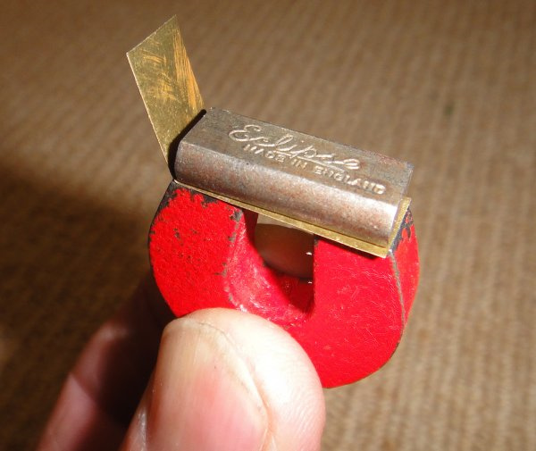
What happened next is still a clear memory.
I was in my home workshop and it was after midnight and time to go to bed, but I couldn't resist the temptation to try out this new idea.
I soon found a horseshoe magnet and a piece of shim brass. I put the shim brass between the magnet and its 'keeper' and bent the brass with my finger!
Eureka! It worked. The brass was only 0.09mm thick but the principle was established!
(The photo at left is a re-construction of the original experiment but it is using the same components).
I was excited because I realised, right from the start, that if the idea could be made to work in a practical way then it would represent a new concept in how to form sheetmetal.
The next day I told my work colleague, Tony Grainger, about my ideas. He was a bit excited too and he sketched out a possible design for an electromagnet for me. He also did some calculations regarding what sort of forces could be achieved from an electromagnet. Tony was the cleverest person that I knew and I was so lucky to have him as a colleague and have access to his considerable expertise.
Well initially it looked like the idea would probably only work for fairly thin gauges of sheetmetal but it was promising enough to encourage me to proceed.
Early Development:
Over the next few days I obtained some pieces of steel, some copper wire, and a rectifier and built my first electro-magnetic folder! I still have it in my workshop:
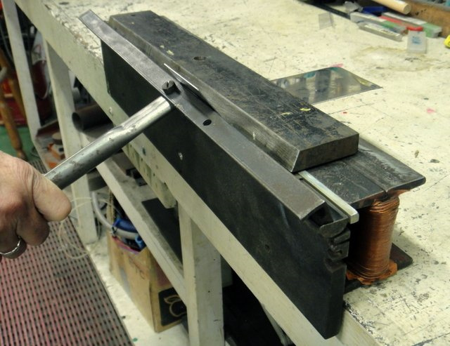
The electro-magnet part of this machine is the genuine original.
(The front pole and bending beam shown here were later modifications).
Although rather crude this machine worked!
As envisaged in my original eureka moment, indeed the clamping bar did not have to be attached to the base of the machine at the ends, at the back, or anywhere. Thus the machine was completely open-ended and open-throated.
But the open-ended aspect could only be fully realised if the hinges for the bending beam were also a bit unconventional.
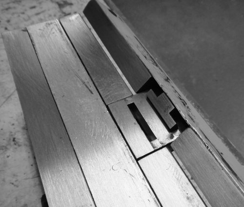
Over the coming months I worked on a kind of half-hinge that I called a 'cup-hinge', I built a better performing machine (Mark II), I lodged a Provisional Patent Specification with the Australian Patent Office and I also appeared on an ABC television programme called "The Inventors". My invention was selected as the winner for that week and later went on to be selected as one of the finalists for that year (1975).
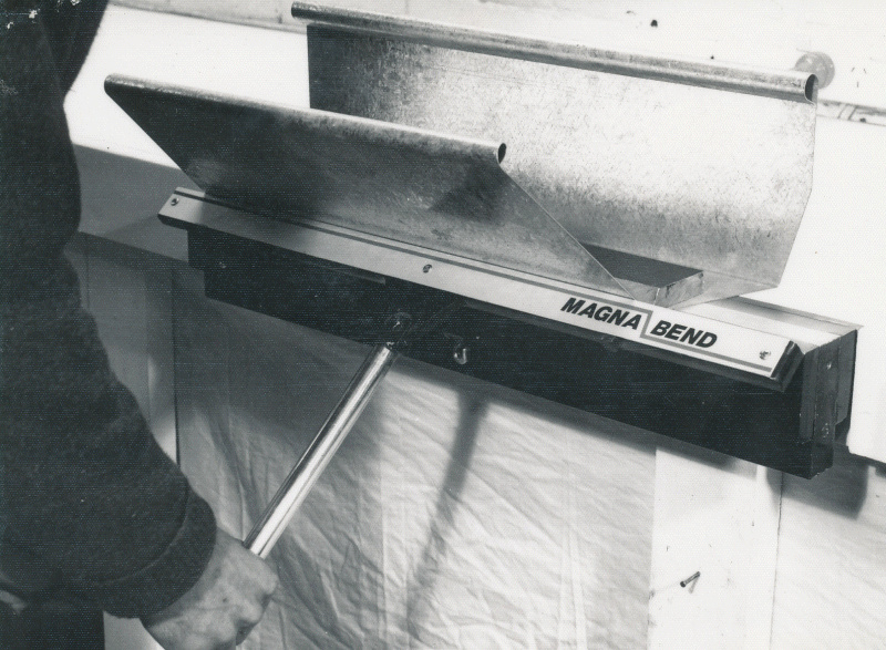
On the left is the Mark II bender as demonstrated in Sydney following the appearance on the final of The Inventors.
It used a more developed version of the 'cup hinge' as shown below:
During 1975 I met Geoff Fenton at an Inventors Association meeting in Hobart (3 August 1975). Geoff was quite interested in the "Magnabend" invention and came back to my place after the meeting to have a closer look at it. This was to be the start of an enduring friendship with Geoff and later a business partnership.
Geoff was an Engineering graduate and a very clever inventor himself. He readily saw the importance of having a hinge design that would allow the machine to realize its full open-ended potential.
My 'cup hinge' worked but had serious problems for beam angles much beyond 90 degrees.
Geoff became very interested in centerless hinges. This class of hinge can provide pivoting around a virtual point which can be completely outside the hinge mechanism itself.
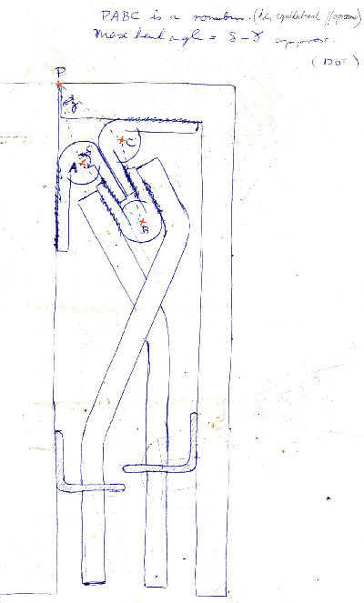
One day (1 Feb 1976) Geoff turned up with a drawing of an unusual and innovative looking hinge. I was amazed! I had never seen anything remotely like it before!
(See drawing at left).
I learned that this is a modified pantograph mechanism involving 4-bar linkages. We never actually made a proper version of this hinge but a few months later Geoff came up with an improved version which we did make.
A cross section of the improved version is shown below:
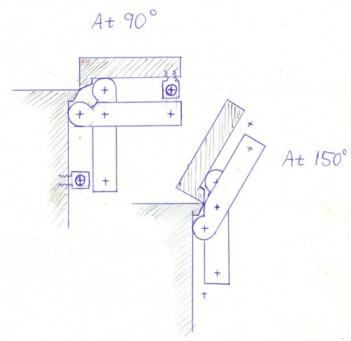
The 'arms' of this hinge are kept parallel to the main pivoting members by small cranks. These can be seen in the photos below. The cranks only have to take a minor percentage of the total hinge load.
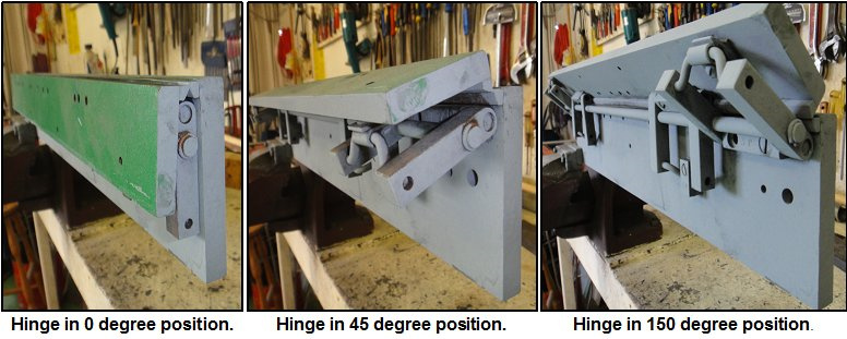
A simulation of this mechanism is shown in the video below. (Thanks to Dennis Aspo for this simulation).
https://youtu.be/wKxGH8nq-tM
Although this hinge mechanism worked quite well, it was never installed on an actual Magnabend machine. Its drawbacks were that it did not provide for a full 180 degree rotation of the bending beam and also it seemed to have a lot of parts in it (although many of the parts were the same as each other).
The other reason that this hinge didn't get used was because Geoff then came up with his:
Triaxial Hinge:
The triaxial hinge did provide for a full 180 degrees of rotation and was simpler inasmuch as it needed fewer parts, although the parts themselves were more complicated.
The triaxial hinge progressed thru several stages before reaching a fairly settled design. We called the different types The Trunnion Hinge, The Spherical Internal Hinge and The Spherical External Hinge.
The spherical external hinge is simulated in the video below (Thank you to Jayson Wallis for this simulation):
https://youtu.be/t0yL4qIwyYU
All of these designs are described in the US Patent Specification document.(PDF).
One of the biggest problems with the Magnabend hinge was that there was nowhere to put it!
The ends of the machine are out because we want the machine to be open-ended, so it has to go somewhere else. There is really no room between the inner face of the bending beam and the outer face of the front pole of the magnet either.
To make room we can provide a lips on the bending beam and on the front pole but these lips compromise the strength of the bending beam and the clamping force of the magnet. (You can see these lips in the photos of the pantograph hinge above).
Thus the hinge design is constrained between the need to be thin so that only small lips will be needed and the need to be thick so that it will be strong enough. And also the need to be centerless so as to provide a virtual pivot, preferably just above the work-surface of the magnet.
These requirements amounted to a very tall order, but Geoff's very inventive design addressed the requirements well, although a lot of development work (extending over at least 10 years) was needed to find the best compromises.
If requested I may write a separate article on the hinges and their development but for now we will return to the history:
Manufacture-Under-Licence Agreements:
Over the coming years we signed a number of "Manufacture-Under-License" agreements:
6 February 1976: Nova Machinery Pty Ltd, Osborne Park, Perth Western Australia.
31 December 1982: Thalmann Konstruktionen AG, Frauenfeld, Switzerland.
12 October 1983: Roper Whitney Co, Rockford, Illinois, USA.
1 December 1983: Jorg Machinefabriek, Amersfoort, Holland
(More history if requested by any interested party).
