MAGNABEND - FUNDAMENTAL DESIGN CONSIDERATIONS
Basic Magnet Design
The Magnabend machine is designed as a powerful DC magnet with limited duty cycle.
The machine consists of 3 basic parts:-
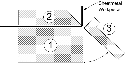
The magnet body which forms the base of the machine and contains the electro-magnet coil.
The clamp bar which provides a path for magnetic flux between the poles of the magnet base, and thereby clamps the sheetmetal workpiece.
The bending beam which is pivoted to the front edge of the magnet body and provides a means for applying bending force to the workpiece.
Magnet-Body Configurations
Various configurations are possible for the magnet body.
Here are 2 that have both been used for Magnabend machines:
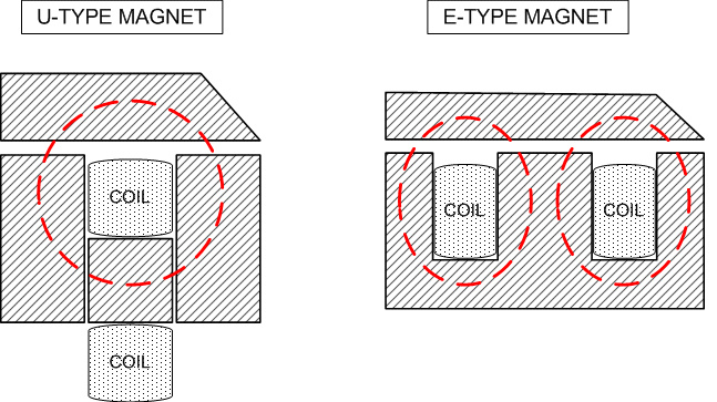
The dashed red lines in the drawings above represent the magnetic flux paths. Note that the "U-Type" design has a single flux pathway (1 pair of poles) whereas the "E-Type" design has 2 flux pathways (2 pairs of poles).
Magnet Configuration Comparison:
The E-type configuration is more efficient than the the U-type configuration.
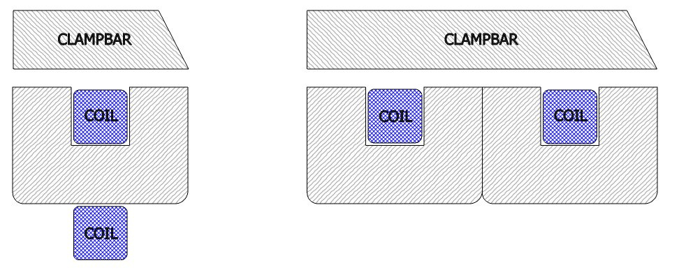
To understand why this is so consider the two drawings below.
On the left is a cross-section of a U-type magnet and on the right is an E-type magnet that has been made by combining 2 of the same U-types. If each magnet configuration is driven by a coil with the same ampere-turns then clearly the doubled-up magnet (the E-type) will have twice as much clamping force. It also uses twice as much steel but hardly any more wire for the coil! (Assuming a long coil design).
(The small amount of extra wire would be needed only because the 2 two legs of the coil are further apart in the "E" design, but this extra becomes insignificant in a long coil design such as used for the Magnabend).
Super Magnabend:
To build an even more powerful magnet the "E" concept can be extended such as this double-E configuration:

3-D Model:
Below is a 3-D drawing showing the basic arrangement of parts in a U-type magnet:
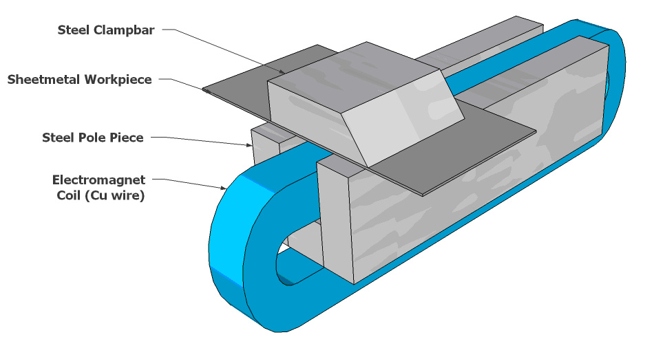
In this design the Front and Rear poles are separate pieces and are attached by bolts to the Core piece.
Although in principle, it would be possible to machine a U-type magnet body from a single piece of steel, it would then not be possible to install the coil and thus the coil would have to be wound in situ (on the machined magnet body).
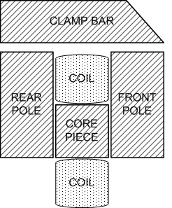
In a production situation it is highly desirable to be able to wind the coils separately (on a special former). Thus a U-type design effectively dictates a fabricated construction.
On the other hand the E-type design lends itself well to a magnet body machined from a single piece of steel because a pre-made coil can easily be installed after the magnet body has been machined. A single-piece magnet body also performs better magnetically as it does not have any construction gaps which would otherwise reduce the magnetic flux (and hence the clamping force) a little.
(Most Magnabends made after 1990 employed the E-type design).
Selection of Material for Magnet Construction
The magnet body and the clampbar must be made from ferromagnetic (magnetisable) material. Steel is by far the cheapest ferromagnetic material and is the obvious choice. However there are various special steels available which might be considered.
1) Silicon Steel : High resistivity steel which is usually available in thin laminations and is used in AC transformers, AC magnets, relays etc. Its properties are not required for the Magnabend which is a DC magnet.
2) Soft Iron : This material would exhibit lower residual magnetism which would be good for a Magnabend machine but it is physically soft which would mean that it would be easily dented and damaged; it is better to solve the residual magnetism problem some other way.
3) Cast Iron : Not as easily magnetised as rolled steel but could be considered.
4) Stainless Steel Type 416 : Cannot be magnetised as strongly as steel and is much more expensive (but may be useful for a thin protective capping surface on the magnet body).
5) Stainless Steel Type 316 : This is a non-magnetic alloy of steel and is therefore not suitable at all (except as in 4 above).
6) Medium Carbon Steel, type K1045 : This material is eminently suitable for the construction of the magnet, (and other parts of the machine). It is reasonably hard in the as-supplied condition and it also machines well.
7) Medium Carbon Steel type CS1020 : This steel is not quite as hard as K1045 but it is more readily available and thus may be the most practical choice for the construction of the Magnabend machine.
Note that the important properties that are required are:
High saturation magnetisation. (Most steel alloys saturate at around 2 Tesla),
Availability of useful section sizes,
Resistance to incidental damage,
Machinability, and
Reasonable cost.
Medium carbon steel fits all these requirements well. Low carbon steel could also be used but it is less resistant to incidental damage. There also exist other special alloys, such as supermendur, which have higher saturation magnetisation but they are not to be considered because of their very high cost compared to steel.
Medium carbon steel does however exhibit some residual magnetism which is enough to be a nuisance. (See section on Residual Magnetism).
The Coil
The coil is what drives the magnetising flux thru the electromagnet. Its magnetising force is just the product of the number of turns (N) and the coil current (I). Thus:

N = number of turns
I = current in the windings.
The appearance of "N" in the above formula leads to a common misconception.
It is widely assumed that increasing the number of turns will increase the magnetising force but generally this does not happen because extra turns also reduce the current, I.
Consider a coil supplied with a fixed DC voltage. If the number of turns is doubled then the resistance of the windings will also be doubled (in a long coil) and thus the current will be halved. The net effect is no increase in NI .
What really determines NI is the resistance per turn. Thus to increase NI the thickness of the wire must be increased. The value of extra turns is that they do reduce current and therefore the power dissipation in the coil.
The designer should be mindful that the wire gauge is what really determines the magnetising force of the coil. This is the most important parameter of coil design.
The NI product is often referred to as the "ampere turns" of the coil.
How Many Ampere Turns are Needed?
Steel exhibits a saturation magnetisation of about 2 Tesla and this sets a fundamental limit on how much clamping force can be obtained.
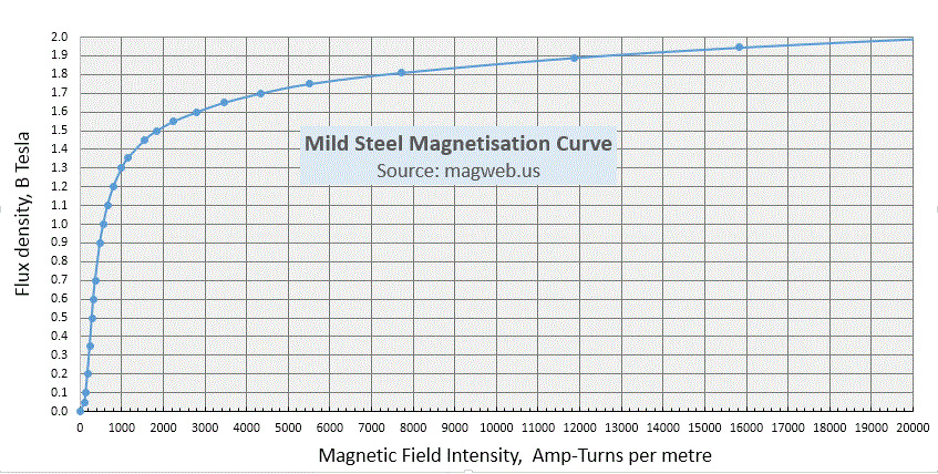
From the above graph we see that the field strength required to get a flux density of 2 Tesla is about 20,000 ampere-turns per metre.
Now, for a typical Magnabend design, the flux path length in the steel is about 1/5th of a meter and therefore will require (20,000/5) AT to produce saturation, that is about 4,000 AT.
It would be nice to have many more ampere turns than this so that saturation magnetisation could be maintained even when non-magnetic gaps (ie non-ferrous workpieces) are introduced into the magnetic circuit. However extra ampere turns can only be gained at considerable cost in power dissipation or cost of copper wire, or both. Thus a compromise is needed.
Typical Magnabend designs have a coil which produces 3,800 ampere turns.
Note that this figure is not dependent on the length of the machine. If the same magnetic design is applied over a range of machine lengths then it dictates that the longer machines will have fewer turns of thicker wire. They will draw more total current but will have the same product of amps x turns and will have the same clamping force (and the same power dissipation) per unit of length.
Duty Cycle
The concept of duty cycle is a very important aspect of the design of the electromagnet. If the design provides for more duty cycle than is needed then it is not optimum. More duty cycle inherently means that more copper wire will be needed (with consequent higher cost) and/or there will be less clamping force available.
Note: A higher duty cycle magnet will have less power dissipation which means that it will use less energy and thus be cheaper to operate. However, because the magnet is ON for only brief periods then the energy cost of operation is usually regarded as being of very little significance. Thus the design approach is to have as much power dissipation as you can get away with in terms of not overheating the windings of the coil. (This approach is common to most electromagnet designs).
The Magnabend is designed for a nominal duty cycle of about 25%.
Typically it takes only 2 or 3 seconds to make a bend. The magnet will then be off for a further 8 to 10 seconds while the workpiece is repositioned and aligned ready for the next bend. If the 25% duty cycle is exceeded then eventually the magnet will get too hot and a thermal overload will trip. The magnet will not be damaged but it will have to be allowed to cool for about 30 minutes before being used again.
Operational experience with machines in the field has shown that the 25% duty cycle is quite adequate for typical users. In fact some users have requested optional high power versions of the machine which have more clamping force at the expense of less duty cycle.
Coil Cross-Sectional Area
The cross sectional area available for the coil will determine the maximum amount of copper wire which can be fitted in. The area available should not be more than is needed, consistent with required ampere turns and power dissipation. Providing more space for the coil will inevitably increase the size of the magnet and result in a longer flux path length in the steel (which will reduce the total flux).
The same argument implies that whatever coil space is provided in the design it should always be full with copper wire. If it is not full then it means that the magnet geometry could have been better.
Magnabend Clamping Force:
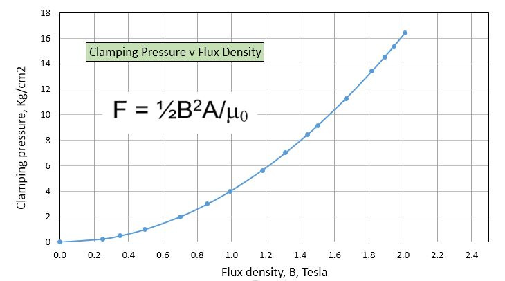
The graph below was obtained by experimental measurements, but it agrees fairly well with theoretical calculations.
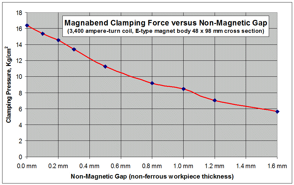
The clamping force can be mathematically calculated from this formula:
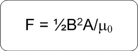
F = force in Newtons
B = magnetic flux density in Teslas
A = area of poles in m2
µ0 = magnetic permeability constant, (4π x 10-7)
For an example we will calculate the clamping force for a flux density of 2 Tesla:
Thus F = ½ (2)2 A/µ0
For a force on unit area (pressure) we can drop the "A" in the formula.
Thus Pressure = 2/µ0 = 2/(4π x 10-7) N/m2.
This comes out to 1,590,000 N/m2.
To convert this to kilograms force it can be divided by g (9.81).
Thus: Pressure = 162,080 kg/m2 = 16.2 kg/cm2.
This agrees rather well with the measured force for a zero gap shown on the above graph.
This figure can easily be converted to a total clamping force for a given machine by multiplying it by the pole area of the machine. For the model 1250E the pole area is 125(1.4+3.0+1.5) =735 cm2.
Thus the total, zero-gap, force would be (735 x 16.2) = 11,900 kg or 11.9 tonnes; about 9.5 tonnes per metre of magnet length .
Flux density and Clamping pressure are directly related and are shown graphed below:
Practical Clamping Force:
In practice this high clamping force is only ever realised when it is not needed(!), that is when bending thin steel workpieces. When bending non-ferrous workpieces the force will be less as shown in the graph above, and (a little curiously), it is also less when bending thick steel workpieces. This is because the clamping force needed to make a sharp bend is very much higher than that needed for a radius bend. So what happens is that as the bend proceeds the front edge of the clampbar lifts slightly thus allowing the workpiece to form a radius.
The small air-gap which is formed causes a slight loss of clamping force but the force needed to form the radius bend has dropped more sharply than has the magnet clamping force. Thus a stable situation results and the clampbar does not let go.
What is described above is the mode of bending when the machine is near its thickness limit. If an even thicker workpiece is tried then of course the clampbar will lift off.
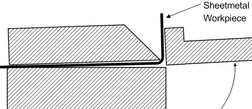
This diagram suggests that if the nose edge of the clampbar was radiused a little, rather than sharp, then the air gap for thick bending would be reduced.
Indeed this is the case and a properly made Magnabend will have a clampbar with a radiused edge. (A radiused edge is also much less prone to accidental damage compared with a sharp edge).
Marginal Mode of Bend Failure:
If a bend is attempted on a very thick workpiece then the machine will fail to bend it because the clampbar will simply lift off. (Fortunately this does not happen in a dramatic way; the clampbar just lets go quietly).
However if the bending load is only slightly greater than the bending capacity of the magnet then generally what happens is that the bend will proceed to say about 60 degrees and then the clampbar will start to slide backwards. In this mode of failure the magnet can only resist the bending load indirectly by creating friction between the workpiece and the bed of the magnet.
The thickness difference between a failure due to lift-off and a failure due to sliding is generally not very much.
Lift-off failure is due to the workpiece levering the front edge of the clampbar upwards. The clamping force at the front edge of the clampbar is mainly what resists this. Clamping at the rear edge has little effect because it is close to where the clampbar is being pivoted. In fact it is only half of the total clamping force which resists lift-off.
On the other hand sliding is resisted by the total clamping force but only via friction so the actual resistance depends on the coefficient of friction between the workpiece and the surface of the magnet.
For clean and dry steel the friction coefficient can be as high as 0.8 but if lubrication is present then it could be as low as 0.2. Typically it will be somewhere in between such that the marginal mode of bend failure is usually due to sliding, but attempts to increase friction on the surface of the magnet have been found to be not worthwhile.
Thickness Capacity:
For an E-type magnet body 98mm wide and 48mm deep and with a 3,800 ampere-turn coil, the full length bending capacity is 1.6mm. This thickness applies to both steel sheet and aluminium sheet. There will be less clamping on the aluminium sheet but it requires less torque to bend it so this compensates in such a way as to give similar gauge capacity for both types of metal.
There needs to be some caveats on the stated bending capacity: The main one being that the yield strength of the sheet metal can vary widely. The 1.6mm capacity applies to steel with a yield stress of up to 250 MPa and to aluminium with a yield stress up to 140 MPa.
The thickness capacity in stainless steel is about 1.0mm. This capacity is significantly less than for most other metals because stainless steel is usually non-magnetic and yet has a reasonably high yield stress.
Another factor is the temperature of the magnet. If the magnet has been allowed to become hot then the resistance of the coil will be higher and this in turn will cause it to draw less current with consequent lower ampere-turns and lower clamping force. (This effect is usually quite moderate and is unlikely to cause the machine to not meet its specifications).
Finally, thicker capacity Magnabends could be made if the magnet cross section was made larger.
